
Topics
All oil and gas engineering topics
OFM Basic: From Excel to Access Database – Practical Step-by-Step Guide
 Production-Surveillance-Intervention — Well and Network Modeling
In many production teams, well and production data are initially compiled in Excel. However, when moving into OFM Basic for analysis, engineers often face difficulties structuring the data correctly into a Microsoft Access database (.mdb).
To address this common challenge, Petrotopic has prepared a practical user guide:
“OFM Basic: From Excel to Database and Open.”
What This Guide Covers
This step-by-step guide explains:
How to prepare Excel sheets properly
How to create tables in Microsoft Access
How to transfer data correctly
How to save the database in .mdb format
How to define the workspace and database in OFM
The guide is written in a simple and practical format, making it suitable for engineers with limited database experience.
Who Should Read This
Junior Production Engineers
Production Technologists
Petroleum Engineering students
Engineers new to OFM Basic
Proper data preparation is the foundation of reliable production analysis. A well-structured database ensures smoother workflow and reduces technical errors inside OFM.
View the user guide here
📥 Download the excel template
Petrotopic will continue sharing practical tools and knowledge to support petroleum engineers in daily operations.
Petrotopic
📄
×
OFM Basic: From Excel to Access Database – Practical Step-by-Step Guide
Production-Surveillance-Intervention — Well and Network Modeling
In many production teams, well and production data are initially compiled in Excel. However, when moving into OFM Basic for analysis, engineers often face difficulties structuring the data correctly into a Microsoft Access database (.mdb).
To address this common challenge, Petrotopic has prepared a practical user guide:
“OFM Basic: From Excel to Database and Open.”
What This Guide Covers
This step-by-step guide explains:
How to prepare Excel sheets properly
How to create tables in Microsoft Access
How to transfer data correctly
How to save the database in .mdb format
How to define the workspace and database in OFM
The guide is written in a simple and practical format, making it suitable for engineers with limited database experience.
Who Should Read This
Junior Production Engineers
Production Technologists
Petroleum Engineering students
Engineers new to OFM Basic
Proper data preparation is the foundation of reliable production analysis. A well-structured database ensures smoother workflow and reduces technical errors inside OFM.
View the user guide here
📥 Download the excel template
Petrotopic will continue sharing practical tools and knowledge to support petroleum engineers in daily operations.
To address this common challenge, Petrotopic has prepared a practical user guide:
“OFM Basic: From Excel to Database and Open.”
What This Guide Covers
This step-by-step guide explains:
How to prepare Excel sheets properly
How to create tables in Microsoft Access
How to transfer data correctly
How to save the database in .mdb format
How to define the workspace and database in OFM
The guide is written in a simple and practical format, making it suitable for engineers with limited database experience.
Who Should Read This
Junior Production Engineers
Production Technologists
Petroleum Engineering students
Engineers new to OFM Basic
Proper data preparation is the foundation of reliable production analysis. A well-structured database ensures smoother workflow and reduces technical errors inside OFM.
View the user guide here
📥 Download the excel template
Petrotopic will continue sharing practical tools and knowledge to support petroleum engineers in daily operations.
IPM User Guide (PVTp, Prosper, MBAL, GAP, Reveal, Resolve, Flow Assurance, OpenServer)
 Production-Surveillance-Intervention — Well and Network Modeling
For students and engineers who are learning petroleum engineering and production workflows, I’m sharing a collection of user guides for commonly used industry software, strictly for education and self-learning purposes.
These guides are helpful to understand:
Basic workflows
Key features and terminology
How different tools are used across reservoir, production, and flow assurance studies
📌 Included topics:
PVTP
Prosper
MBAL
GAP
Reveal
Resolve
Flow Assurance
OpenServer
If you’re a student, junior engineer, or someone refreshing fundamentals, these documents can save you a lot of time and give you better context before hands-on practice.
Feel free to bookmark, share, or comment if you find this useful 👍
#PetroleumEngineering #ProductionEngineering #ReservoirEngineering #FlowAssurance #EngineeringEducation #LearningResources
🔗 Access the user guides below:
PVTp User Guide
PROSPER User Guide
MBAL User Guide
GAP User Guide
Reveal User Guide
RESOLVE User Guide
Flow-Assurance User Guide
OpenServer User Guide
WELLCAT™ casing design software
 Drilling & Completion — Completion
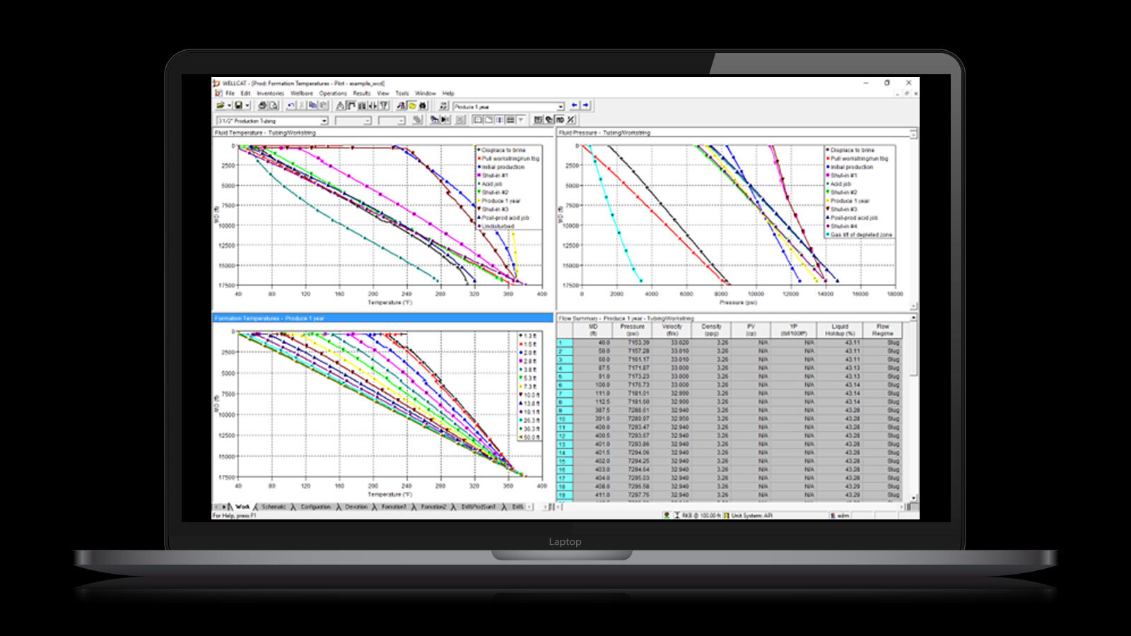
Drill design: Provides transient thermal and fluid flow analysis for drilling operations. Simulations include cementing temperatures, downhole tool temperatures, circulating mud temperatures and other applications.
Casing design: Analyzes casing loads, design integrity, and buckling behavior under complex mechanical, fluid pressure, and thermal loading conditions. Installation and service loads can be defined by standard load cases, or linked to analyses performed with the Drill and Prod modules.
Prod design: Allows for thermal simulation of production operations. These include fluid circulation, liquid and gas injection, fluid production, shut-in, reactive gel treatment, cement squeeze, spotting cement plugs and gas-lift operations.
Tube design: Analyzes tubing loads and movements, buckling behavior, and design integrity, under complex mechanical, fluid pressure, and thermal loading conditions. Installation and service loads can be defined by standard load cases, or linked to analyses performed with the Prod module
Multi-string design: Predicts pressure and volume changes due to annular pressure build up when the well system heats up as a result of production operations or the injection of hot fluids into the well.
WellCat software is a Halliburton Landmark engineering application used in the oil and gas industry for designing and analyzing well casings and tubing, simulating complex temperature and pressure conditions, and ensuring well integrity for drilling, completion, and production, especially in High Pressure/High Temperature (HP/HT) environments, helping engineers optimize designs and reduce costs.
Wellcat User Guide is here
Petrotopic
📄
×
WELLCAT™ casing design software
Drilling & Completion — Completion
Drill design: Provides transient thermal and fluid flow analysis for drilling operations. Simulations include cementing temperatures, downhole tool temperatures, circulating mud temperatures and other applications.
Casing design: Analyzes casing loads, design integrity, and buckling behavior under complex mechanical, fluid pressure, and thermal loading conditions. Installation and service loads can be defined by standard load cases, or linked to analyses performed with the Drill and Prod modules.
Prod design: Allows for thermal simulation of production operations. These include fluid circulation, liquid and gas injection, fluid production, shut-in, reactive gel treatment, cement squeeze, spotting cement plugs and gas-lift operations.
Tube design: Analyzes tubing loads and movements, buckling behavior, and design integrity, under complex mechanical, fluid pressure, and thermal loading conditions. Installation and service loads can be defined by standard load cases, or linked to analyses performed with the Prod module
Multi-string design: Predicts pressure and volume changes due to annular pressure build up when the well system heats up as a result of production operations or the injection of hot fluids into the well.
WellCat software is a Halliburton Landmark engineering application used in the oil and gas industry for designing and analyzing well casings and tubing, simulating complex temperature and pressure conditions, and ensuring well integrity for drilling, completion, and production, especially in High Pressure/High Temperature (HP/HT) environments, helping engineers optimize designs and reduce costs.
Wellcat User Guide is here
Casing design: Analyzes casing loads, design integrity, and buckling behavior under complex mechanical, fluid pressure, and thermal loading conditions. Installation and service loads can be defined by standard load cases, or linked to analyses performed with the Drill and Prod modules.
Prod design: Allows for thermal simulation of production operations. These include fluid circulation, liquid and gas injection, fluid production, shut-in, reactive gel treatment, cement squeeze, spotting cement plugs and gas-lift operations.
Tube design: Analyzes tubing loads and movements, buckling behavior, and design integrity, under complex mechanical, fluid pressure, and thermal loading conditions. Installation and service loads can be defined by standard load cases, or linked to analyses performed with the Prod module
Multi-string design: Predicts pressure and volume changes due to annular pressure build up when the well system heats up as a result of production operations or the injection of hot fluids into the well.
WellCat software is a Halliburton Landmark engineering application used in the oil and gas industry for designing and analyzing well casings and tubing, simulating complex temperature and pressure conditions, and ensuring well integrity for drilling, completion, and production, especially in High Pressure/High Temperature (HP/HT) environments, helping engineers optimize designs and reduce costs.
Wellcat User Guide is here
ESP Design – Hand Calculations guide
The ESP Design – Hand Calculations guide provides a step-by-step walkthrough for designing an Electrical Submersible Pump (ESP) system, especially useful for wells producing water and light crude oil. Here's a summary of the 9-step design procedure:
🧩 1. Basic Data Collection
Well profile, casing, tubing, perforation depth
Fluid properties: API gravity, water cut, GOR, pressures, temperatures
Production targets and power availability
📈 2. Production Capacity
Uses Productivity Index (PI) to estimate inflow performance
Calculates flowing bottomhole pressure (Pwf) and pump intake pressure (PIP)
💨 3. Gas Calculations
Determines free gas volume at pump intake
Uses Standing’s correlation for solution GOR
Calculates oil and gas formation volume factors (Bo and Bg)
📏 4. Total Dynamic Head (TDH)
Combines net well lift, tubing friction loss, and wellhead pressure head
Uses Hazen-Williams formula for friction loss
🔄 5. Pump Type Selection
Chooses pump series based on casing size and flow rate
Calculates number of stages and required brake horsepower (BHP)
⚙️ 6. Compound Sizing
Selects seal, motor, and evaluates gas separator need
Motor selection considers frequent starts/stops and voltage requirements
🔌 7. Cable Selection
Determines cable size, type, and length
Calculates voltage drop and power loss for cost analysis
🛠️ 8. Accessory Equipment
Includes motor lead extension, cable bands, protectors, check valves
Surface equipment like Variable Frequency Drive (VFD) and transformer taps
📊 9. Final System Integration
Ensures all components are compatible and optimized for performance and cost.
ESP Design Form is here
Petrotopic
📄
×
ESP Design – Hand Calculations guide
Production-Surveillance-Intervention — Artificial Lift
The ESP Design – Hand Calculations guide provides a step-by-step walkthrough for designing an Electrical Submersible Pump (ESP) system, especially useful for wells producing water and light crude oil. Here's a summary of the 9-step design procedure:
🧩 1. Basic Data Collection
Well profile, casing, tubing, perforation depth
Fluid properties: API gravity, water cut, GOR, pressures, temperatures
Production targets and power availability
📈 2. Production Capacity
Uses Productivity Index (PI) to estimate inflow performance
Calculates flowing bottomhole pressure (Pwf) and pump intake pressure (PIP)
💨 3. Gas Calculations
Determines free gas volume at pump intake
Uses Standing’s correlation for solution GOR
Calculates oil and gas formation volume factors (Bo and Bg)
📏 4. Total Dynamic Head (TDH)
Combines net well lift, tubing friction loss, and wellhead pressure head
Uses Hazen-Williams formula for friction loss
🔄 5. Pump Type Selection
Chooses pump series based on casing size and flow rate
Calculates number of stages and required brake horsepower (BHP)
⚙️ 6. Compound Sizing
Selects seal, motor, and evaluates gas separator need
Motor selection considers frequent starts/stops and voltage requirements
🔌 7. Cable Selection
Determines cable size, type, and length
Calculates voltage drop and power loss for cost analysis
🛠️ 8. Accessory Equipment
Includes motor lead extension, cable bands, protectors, check valves
Surface equipment like Variable Frequency Drive (VFD) and transformer taps
📊 9. Final System Integration
Ensures all components are compatible and optimized for performance and cost.
ESP Design Form is here
DTS, DAS With MARS (Weatherford)
 Production-Surveillance-Intervention — Surveillance
The energy industry’s most advanced thru-tubing intervention and reservoir-intelligence system. Unified sensors provide distributed-acoustic (DAS), distributed-temperature (DTS) and optical pressure-and-temperature (P/T) data-feeds including non-nuclear, multiphase-flow metering—all in real time. MARS delivers a cost-effective imagery solution that spans the entire length of any well to enable mature-well reservoir enhancement.
ADVANCED REAL-TIME WELL MANAGEMENT: Integrated DAS, DTS, and PT sensors provide continuous, high-resolution data in real time for optimized production and proactive reservoir management. Instantly identify fluids in the full range of water cut and gas-void fraction (GVF) with the near-infrared (NIR) sensitivity of the multiphase flowmeter (MPFM). Non-intrusive, venturi-affect sonar accurately measures oil and gas and gas liquid ratios without interruption from flow regimes or slugging by sensing turbulent fluid movement between sensors
ENHANCED REMEDIAL INTERVENTION: Proactive intervention starts with immediate well data. Non-nuclear flow measurements provide ultra-precise multiphase support that eliminates dedicated separator equipment and frequent human intervention, reducing operating expenses by up to 70%. Identify cased-hole integrity and performance with target detection to improve communication for hydraulic fracturing and interpret data for quick analysis and decision making with advanced wellsite visualization.
STREAMLINEDDEPLOYMENT FLEXIBILITY: High-endurance fiberline installation enables a rigless intervention for advanced monitoring in deep, geothermal wells while offering low upfront cost and eliminating the CAPEX requirements. Modular and mobile deployment capabilities along with a single fiberline conveyance simplifies and streamlines operations for even the most challenging wells, minimizing HSE risk and redzone exposure and improving carbon footprint.
Petrotopic
📄
×
DTS, DAS With MARS (Weatherford)
Production-Surveillance-Intervention — Surveillance
The energy industry’s most advanced thru-tubing intervention and reservoir-intelligence system. Unified sensors provide distributed-acoustic (DAS), distributed-temperature (DTS) and optical pressure-and-temperature (P/T) data-feeds including non-nuclear, multiphase-flow metering—all in real time. MARS delivers a cost-effective imagery solution that spans the entire length of any well to enable mature-well reservoir enhancement.
ADVANCED REAL-TIME WELL MANAGEMENT: Integrated DAS, DTS, and PT sensors provide continuous, high-resolution data in real time for optimized production and proactive reservoir management. Instantly identify fluids in the full range of water cut and gas-void fraction (GVF) with the near-infrared (NIR) sensitivity of the multiphase flowmeter (MPFM). Non-intrusive, venturi-affect sonar accurately measures oil and gas and gas liquid ratios without interruption from flow regimes or slugging by sensing turbulent fluid movement between sensors
ENHANCED REMEDIAL INTERVENTION: Proactive intervention starts with immediate well data. Non-nuclear flow measurements provide ultra-precise multiphase support that eliminates dedicated separator equipment and frequent human intervention, reducing operating expenses by up to 70%. Identify cased-hole integrity and performance with target detection to improve communication for hydraulic fracturing and interpret data for quick analysis and decision making with advanced wellsite visualization.
STREAMLINEDDEPLOYMENT FLEXIBILITY: High-endurance fiberline installation enables a rigless intervention for advanced monitoring in deep, geothermal wells while offering low upfront cost and eliminating the CAPEX requirements. Modular and mobile deployment capabilities along with a single fiberline conveyance simplifies and streamlines operations for even the most challenging wells, minimizing HSE risk and redzone exposure and improving carbon footprint.

Well Leak Detector With Vivid
 Production-Surveillance-Intervention — Leaking
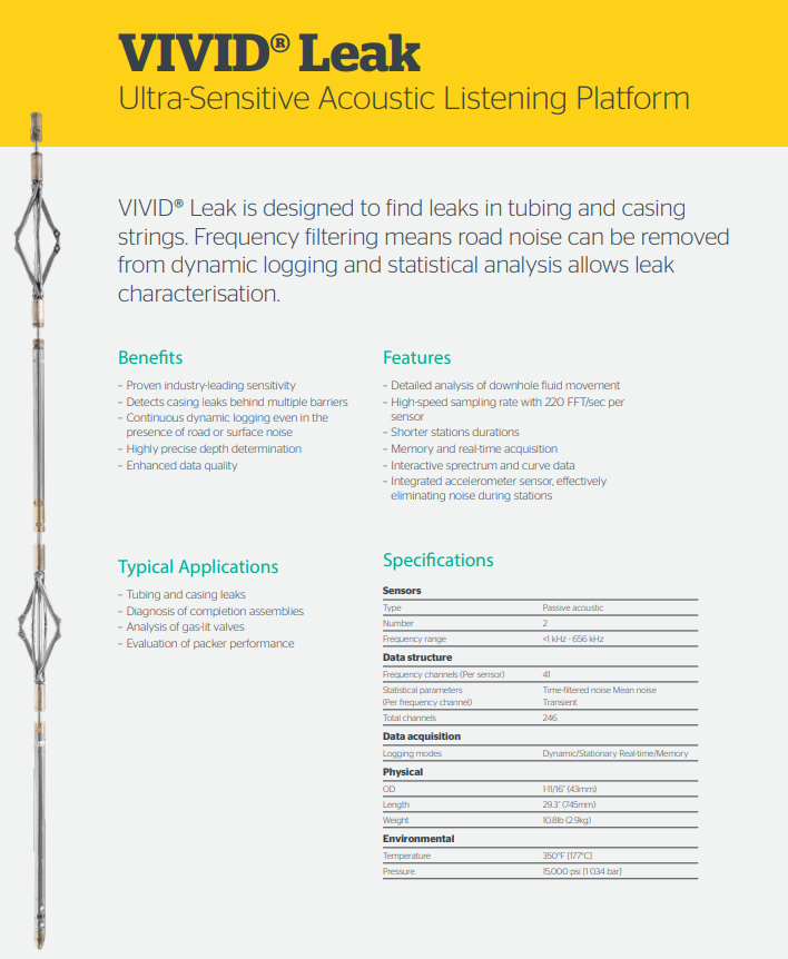
VIVID® Leak is designed to find leaks in tubing and casing strings. Frequency filtering means road noise can be removed from dynamic logging and statistical analysis allows leak characterization.
The VIVID platform consists of full-spectrum acoustic sensors that accurately measure the broadest frequency bandwidth and amplitude of acoustic energy with industry-leading sensitivity and can even locate previously indiscernible low energy leaks. Developed by Archer’s Research and Development team and independently-tested, VIVID will play a key role in casing and completion evaluation, cement performance evaluation and turbulent flow analysis.
“Our VIVID acoustic listening platform represents a major turning point in the industry – detecting leaks that were previously undetectable and generating previously unavailable downhole information,” said Peter Kleinbichler, Wireline Vice President Sales & Marketing at Archer.
He continues: “With an increased industry focus on efficiencies, costs and safety, VIVID is the right technology for the right time — providing the clearest answers yet on downhole events, improving oil and gas performance, and providing documented evidence that operators are addressing safety and regulatory requirements during both the operational and P&A phases of the well lifecycle.”
Key applications include:
+ Casing and completion evaluation with the acoustic technology able to detect leaks while logging dynamically in the presence of road or surface noise; characterise leak responses in gas and liquid, and gas bubble flow; locate gas migration behind casing that was previously below detection thresholds and identify cross flow behind perforations.
+ Cement performance evaluation with VIVID determining the sealing quality of the cement; evaluating flow in the presence of micro-annuli; and establishing minimum flow levels through a cement barrier.
+ Turbulence mapping where turbulent flow can be mapped in real time with VIVID's full broadband spectrum and sensitivity supporting production flow characterisation and mitigation of completion damage.
Petrotopic
📄
×
Well Leak Detector With Vivid
Production-Surveillance-Intervention — Leaking
VIVID® Leak is designed to find leaks in tubing and casing strings. Frequency filtering means road noise can be removed from dynamic logging and statistical analysis allows leak characterization.
The VIVID platform consists of full-spectrum acoustic sensors that accurately measure the broadest frequency bandwidth and amplitude of acoustic energy with industry-leading sensitivity and can even locate previously indiscernible low energy leaks. Developed by Archer’s Research and Development team and independently-tested, VIVID will play a key role in casing and completion evaluation, cement performance evaluation and turbulent flow analysis.
“Our VIVID acoustic listening platform represents a major turning point in the industry – detecting leaks that were previously undetectable and generating previously unavailable downhole information,” said Peter Kleinbichler, Wireline Vice President Sales & Marketing at Archer.
He continues: “With an increased industry focus on efficiencies, costs and safety, VIVID is the right technology for the right time — providing the clearest answers yet on downhole events, improving oil and gas performance, and providing documented evidence that operators are addressing safety and regulatory requirements during both the operational and P&A phases of the well lifecycle.”
Key applications include:
+ Casing and completion evaluation with the acoustic technology able to detect leaks while logging dynamically in the presence of road or surface noise; characterise leak responses in gas and liquid, and gas bubble flow; locate gas migration behind casing that was previously below detection thresholds and identify cross flow behind perforations.
+ Cement performance evaluation with VIVID determining the sealing quality of the cement; evaluating flow in the presence of micro-annuli; and establishing minimum flow levels through a cement barrier.
+ Turbulence mapping where turbulent flow can be mapped in real time with VIVID's full broadband spectrum and sensitivity supporting production flow characterisation and mitigation of completion damage.
The VIVID platform consists of full-spectrum acoustic sensors that accurately measure the broadest frequency bandwidth and amplitude of acoustic energy with industry-leading sensitivity and can even locate previously indiscernible low energy leaks. Developed by Archer’s Research and Development team and independently-tested, VIVID will play a key role in casing and completion evaluation, cement performance evaluation and turbulent flow analysis.
“Our VIVID acoustic listening platform represents a major turning point in the industry – detecting leaks that were previously undetectable and generating previously unavailable downhole information,” said Peter Kleinbichler, Wireline Vice President Sales & Marketing at Archer.
He continues: “With an increased industry focus on efficiencies, costs and safety, VIVID is the right technology for the right time — providing the clearest answers yet on downhole events, improving oil and gas performance, and providing documented evidence that operators are addressing safety and regulatory requirements during both the operational and P&A phases of the well lifecycle.”
Key applications include:
+ Casing and completion evaluation with the acoustic technology able to detect leaks while logging dynamically in the presence of road or surface noise; characterise leak responses in gas and liquid, and gas bubble flow; locate gas migration behind casing that was previously below detection thresholds and identify cross flow behind perforations.
+ Cement performance evaluation with VIVID determining the sealing quality of the cement; evaluating flow in the presence of micro-annuli; and establishing minimum flow levels through a cement barrier.
+ Turbulence mapping where turbulent flow can be mapped in real time with VIVID's full broadband spectrum and sensitivity supporting production flow characterisation and mitigation of completion damage.
Gaslift Valves
Production-Surveillance-Intervention — SurvaillanceLeucipa by Baker Huges
 Digital Platform In Market — Digital Platform
Leucipa is an automated field production solution developed by Baker Hughes. It focuses on helping oil and gas operators proactively manage production and reduce carbon emissions through intelligent operations and data-driven insights Baker Hughes. Leucipa connects a network of digital production technologies, ensuring analytics work across applications and enabling a unified experience for maximizing assets YouTube.
Here's a more detailed breakdown:
Automated Field Production:
Leucipa aims to automate various aspects of field operations, from production processes to managing electric submersible pumps (ESPs).
Digital Transformation:
It's a digital solution that connects the entire production ecosystem, from the edge to the cloud.
Data-Driven Insights:
Leucipa leverages data to optimize production, minimize inefficiencies, and ensure environmentally sound operations.
ESP Optimization:
A key component is the Leucipa ESP Optimizer, which analyzes and optimizes ESP performance, predicts run-life, and detects potential issues.
Customer-Centric Approach:
The solution is designed to be configurable and adaptable to specific customer needs and field conditions.
Focus on Sustainability:
Leucipa helps customers recover untapped resources and minimize environmental impact.
Partnership with Amazon Web Services:
Leucipa is powered by AWS, allowing for scalability and cloud-based operations.
Read More
Petrotopic
📄
×
Leucipa by Baker Huges
Digital Platform In Market — Digital Platform
Leucipa is an automated field production solution developed by Baker Hughes. It focuses on helping oil and gas operators proactively manage production and reduce carbon emissions through intelligent operations and data-driven insights Baker Hughes. Leucipa connects a network of digital production technologies, ensuring analytics work across applications and enabling a unified experience for maximizing assets YouTube.
Here's a more detailed breakdown:
Automated Field Production:
Leucipa aims to automate various aspects of field operations, from production processes to managing electric submersible pumps (ESPs).
Digital Transformation:
It's a digital solution that connects the entire production ecosystem, from the edge to the cloud.
Data-Driven Insights:
Leucipa leverages data to optimize production, minimize inefficiencies, and ensure environmentally sound operations.
ESP Optimization:
A key component is the Leucipa ESP Optimizer, which analyzes and optimizes ESP performance, predicts run-life, and detects potential issues.
Customer-Centric Approach:
The solution is designed to be configurable and adaptable to specific customer needs and field conditions.
Focus on Sustainability:
Leucipa helps customers recover untapped resources and minimize environmental impact.
Partnership with Amazon Web Services:
Leucipa is powered by AWS, allowing for scalability and cloud-based operations.
Read More
Carbonate Stimulation
Production-Surveillance-Intervention — Stimulation
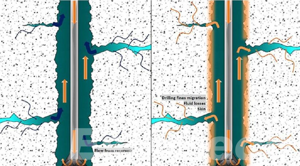
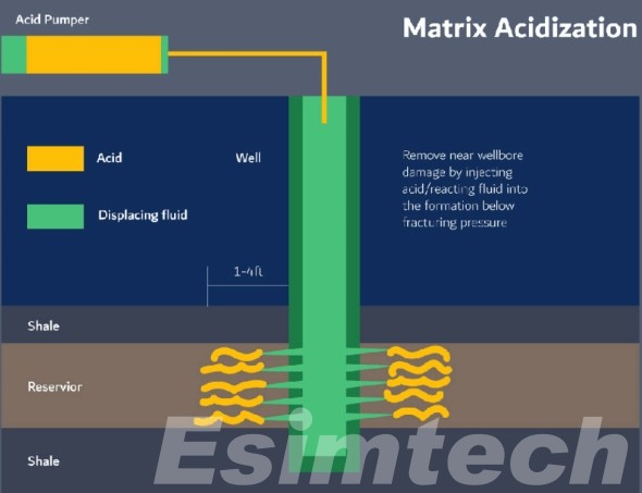
Acid stimulation in carbonate reservoirs involves using acidic fluids to enhance oil or gas production by increasing the reservoir's permeability. This is achieved by dissolving the carbonate rock and creating or widening flow paths, such as wormholes, that connect the wellbore to the reservoir. The process can be categorized into matrix acidizing (at sub-fracturing pressures) and acid fracturing (creating fractures).
Here's a more detailed breakdown:
1. What is Stimulation?
Purpose:
To improve the flow of hydrocarbons from the reservoir to the wellbore by increasing the permeability of the rock.
Why in Carbonates?
Carbonate reservoirs often have low permeability due to their complex pore structure and mineralogy.
How it Works:
Acid reacts with the carbonate rock, dissolving it and creating channels or widening existing ones.
2. Matrix Acidizing:
Process:
Acid is injected into the wellbore at pressures below the fracture pressure of the rock.
Goal:
To remove near-wellbore damage (e.g., drilling mud, scale buildup) and improve the permeability of the formation around the wellbore.
Suitable for:
High-permeability reservoirs where the acid can flow through the rock and dissolve material.
3. Acid Fracturing:
Process:
Acid is injected at higher pressures, fracturing the rock and creating new pathways.
Goal:
To create longer, more conductive fractures that extend further into the reservoir.
Suitable for:
Low-permeability reservoirs where fracturing is necessary to create significant flow paths.
4. Key Aspects of Carbonate Acid Stimulation:
Wormhole Formation:
In both matrix acidizing and acid fracturing, the acid creates wormholes (highly conductive channels) that can significantly improve flow.
Acid Selection:
The choice of acid (e.g., hydrochloric acid (HCl), EDTA) depends on the reservoir conditions, rock type, and desired outcome.
Additives:
Additives can be used to modify the acid's properties (e.g., viscosity, reactivity) to optimize the stimulation process.
Rock Properties:
Mineralogy, pore structure, and heterogeneity of the carbonate rock all influence the effectiveness of acid stimulation.
5. Factors Affecting Success:
Injection Rate:
The rate at which acid is injected affects wormhole morphology and stimulation efficiency.
Acid Concentration and Volume:
Proper selection of acid type and concentration is crucial for achieving desired results.
Reservoir Heterogeneity:
The presence of different rock types or variations in pore structure can affect how the acid flows and reacts.
Temperature and Pressure:
These factors can influence the reaction rate and the overall effectiveness of the stimulation treatment.
Read More
GOR (Gas-Oil Ratio) Trends
 Production-Surveillance-Intervention — Well and Network Modeling
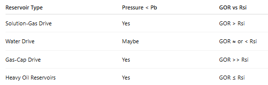
GOR can be lower, equal, or higher than Rsi depending on the reservoir type and drive mechanism
1. Depletion-Drive (Solution-Gas Drive) Reservoirs
When pressure drops below Pb → gas evolves → flows with oil.
GOR increases above Rsi.
Eventually, GOR can peak, then decline as oil rate drops faster.
✅ GOR > Rsi (typical behavior)
2. Water-Drive Reservoirs
Pressure may stay near bubble point longer.
Less gas liberation.
GOR may remain close to Rsi or even below Rsi if gas is trapped or segregated.
✅ GOR ≈ Rsi or GOR < Rsi
3. Gas-Cap Drive Reservoirs
If gas cap is produced → very high GOR.
If only oil zone is produced → GOR may increase moderately.
GOR can be much higher than Rsi depending on coning or breakthrough.
✅ GOR > Rsi (if gas cap coning occurs)
4. Heavy Oil Reservoirs
Low Rsi to begin with.
Gas mobility is low.
GOR can remain low or increase slowly.
✅ GOR may stay ≤ Rsi for long time
Read More
Stimulation In Carbonate
 Production-Surveillance-Intervention — Stimulation
In Carbonate, there are two types of acid to be used
Read More
Read More
Stimulation Notes
 Production-Surveillance-Intervention — Stimulation
RMP
Reservoir Engineering — Reservoir ModelingReserve
Reservoir Engineering — Reservoir Management Plan
Reserve Calculation
Water Shutoff
Production-Surveillance-Intervention — Water Shutoff
Formation Damage
Production-Surveillance-Intervention — StimulationGravel Pack
Production-Surveillance-Intervention — Sand ControlSand Control
Production — Sand ControlWell model
 Production-Surveillance-Intervention — Well and Network Modeling
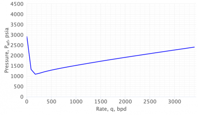
The Beggs & Brill correlation is widely used in PROSPER to estimate pressure drop in multiphase flow. The total pressure gradient is:
\[
\frac{dP}{dL} = \left( \frac{dP}{dL} \right)_{\text{elevation}} + \left( \frac{dP}{dL} \right)_{\text{friction}} + \left( \frac{dP}{dL} \right)_{\text{acceleration}}
\]
Where:
- \(\left( \frac{dP}{dL} \right)_{\text{elevation}} = \rho_m \cdot g \cdot \sin(\theta)\)
- \(\left( \frac{dP}{dL} \right)_{\text{friction}} = \frac{f \cdot \rho_m \cdot v_m^2}{2D}\)
- \(\left( \frac{dP}{dL} \right)_{\text{acceleration}} = \frac{d(\rho_m v_m)}{dt}\)
**Image example below shows a typical VLP curve from PROSPER:**
Read More
\[
\frac{dP}{dL} = \left( \frac{dP}{dL} \right)_{\text{elevation}} + \left( \frac{dP}{dL} \right)_{\text{friction}} + \left( \frac{dP}{dL} \right)_{\text{acceleration}}
\]
Where:
- \(\left( \frac{dP}{dL} \right)_{\text{elevation}} = \rho_m \cdot g \cdot \sin(\theta)\)
- \(\left( \frac{dP}{dL} \right)_{\text{friction}} = \frac{f \cdot \rho_m \cdot v_m^2}{2D}\)
- \(\left( \frac{dP}{dL} \right)_{\text{acceleration}} = \frac{d(\rho_m v_m)}{dt}\)
**Image example below shows a typical VLP curve from PROSPER:**
The Beggs & Brill correlation is widely used in PROSPER to estimate pressure drop in multiphase flow. The total pressure gradient is:
\[
\frac{dP}{dL} = \left( \frac{dP}{dL} \right)_{\text{elevation}} + \left( \frac{dP}{dL} \right)_{\text{friction}} + \left( \frac{dP}{dL} \right)_{\text{acceleration}}
\]
Where:
- \(\left( \frac{dP}{dL} \right)_{\text{elevation}} = \rho_m \cdot g \cdot \sin(\theta)\)
- \(\left( \frac{dP}{dL} \right)_{\text{friction}} = \frac{f \cdot \rho_m \cdot v_m^2}{2D}\)
- \(\left( \frac{dP}{dL} \right)_{\text{acceleration}} = \frac{d(\rho_m v_m)}{dt}\)
**Image example below shows a typical VLP curve from PROSPER:**
Read More
Petrotopic
📄
×
Well model
Production-Surveillance-Intervention — Well and Network Modeling
The Beggs & Brill correlation is widely used in PROSPER to estimate pressure drop in multiphase flow. The total pressure gradient is:
\[
\frac{dP}{dL} = \left( \frac{dP}{dL} \right)_{\text{elevation}} + \left( \frac{dP}{dL} \right)_{\text{friction}} + \left( \frac{dP}{dL} \right)_{\text{acceleration}}
\]
Where:
- \(\left( \frac{dP}{dL} \right)_{\text{elevation}} = \rho_m \cdot g \cdot \sin(\theta)\)
- \(\left( \frac{dP}{dL} \right)_{\text{friction}} = \frac{f \cdot \rho_m \cdot v_m^2}{2D}\)
- \(\left( \frac{dP}{dL} \right)_{\text{acceleration}} = \frac{d(\rho_m v_m)}{dt}\)
**Image example below shows a typical VLP curve from PROSPER:**
Read More
\[
\frac{dP}{dL} = \left( \frac{dP}{dL} \right)_{\text{elevation}} + \left( \frac{dP}{dL} \right)_{\text{friction}} + \left( \frac{dP}{dL} \right)_{\text{acceleration}}
\]
Where:
- \(\left( \frac{dP}{dL} \right)_{\text{elevation}} = \rho_m \cdot g \cdot \sin(\theta)\)
- \(\left( \frac{dP}{dL} \right)_{\text{friction}} = \frac{f \cdot \rho_m \cdot v_m^2}{2D}\)
- \(\left( \frac{dP}{dL} \right)_{\text{acceleration}} = \frac{d(\rho_m v_m)}{dt}\)
**Image example below shows a typical VLP curve from PROSPER:**
The Beggs & Brill correlation is widely used in PROSPER to estimate pressure drop in multiphase flow. The total pressure gradient is:
\[
\frac{dP}{dL} = \left( \frac{dP}{dL} \right)_{\text{elevation}} + \left( \frac{dP}{dL} \right)_{\text{friction}} + \left( \frac{dP}{dL} \right)_{\text{acceleration}}
\]
Where:
- \(\left( \frac{dP}{dL} \right)_{\text{elevation}} = \rho_m \cdot g \cdot \sin(\theta)\)
- \(\left( \frac{dP}{dL} \right)_{\text{friction}} = \frac{f \cdot \rho_m \cdot v_m^2}{2D}\)
- \(\left( \frac{dP}{dL} \right)_{\text{acceleration}} = \frac{d(\rho_m v_m)}{dt}\)
**Image example below shows a typical VLP curve from PROSPER:**
Read More
Page 1 of 1
Petrotopic is all about Petroleum Engineering Topics
Social Media
📘 Petrotopic Article on LinkedIn
Discover insights, innovations, and trends in petroleum engineering directly from Petrotopic.
➤ View Full Article on LinkedIn